
3.1 Camera Systems
A camera system is composed of the camera body, lens, diaphragm, shutter and a film (Figure 3.1):
Figure 3.1. Components of a camera system
Lens collects the energy and it has a focal length. Diaphragm controls the amount of energy reaching the film with an adjustable diameter Shutter works by open and close. The time period between the open and close controls the amount of energy entering into the camera. The principle of imaging is described by:
where
f = focal length
do = distance from the lens to the object
di = distance from the lens to the image (Figure 3.2)For aerial photography,
do >> di
Therefore, we have a fixed distance between the lens to the film.
Figure 3.2. The imaging optics
The diameter of a diaphragm controls the depth of field. The smaller the diameter of an opened diaphram, the wider the distance range in which the scene constructs clearly focused image. The diaphragm diameter can be adjusted to a particular aperture. What we normally see on a camera's aperture setting is F 2.8 4 5.6 8 11 16 22
These F#s are obtained by f/diameter. When diameter becomes smaller, F# becomes larger and more energy is stopped. The actual amount of energy reaching the film is determined by:

where
i is the energy intensity J/m2ïs
t is time in second
F is F# as mentioned above
E is energy in J/m2A film is primarily composed of an emulsion layer(s) and base (Figure 3.3)

Black and white film Color film Figure 3.3. Layers in black and white films and colour films
The most important part of the film is the emulsion layer. An emulsion layer contains light sensitive chemicals. When it is exposed in the light, chemical reaction occurs and a latent image is formed. After developing the film, the emulsion layer will show the image.
Films can be divided into negative and positive, or divided in terms of their ranges of spectral sensitivities: black and white (B/W), B/W Infrared, Color, Color Infrared.
B/W negative films are those films that have the brightest part of the scene appearing the darkest while the darker part of the scene appearing brighter on a developed film.
Color negative films are those on which a color from the scene is recorded by its complementary colors.
There are two important aspects of a film: its spectral sensitivity and its characteristic curve.
Spectral sensitivity specifies the spectral region to which a film is sensitive (Figure 3.4).
Figure 3.4. The sensitivity of films and the transmittance of a filter
Since infrared is also sensitive to visible light, the visible light should be intercepted by some material. This is done by optical filtering (Figure 3.4). For this case, a dark red filter can be used to intercept visible light.
Similarly, other filters can be used to stop light at certain spectral ranges from reaching the film.
Characteristic curve indicates the radiative response of a film to the energy level.

[a] [b] Figure 3.5. Film characteristic curves.
If the desnity of a film develops quickly when the film is exposed to light, we say that the film is fast (Fig. 3.5a). Otherwise, the film is slow (Fig. 3.5b). Film speed is defined by labels such as ASA 100, ASA 200, ...., ASA 1000. The greater the ASA number, the faster a film is. High speed films will have a good contrast on the image, but low speed films will provide better details.
There are two types of colors: additive primaries and subtractive primaries:
ï Three additive primaries are red, green, and blue
ï Three subtractive primaries are cyan, magenta, and yellow
All colors can be made by combining any two primary colors.

Figure 3.6. Additive and subtractive colors
Additive colors apply to the mixing of light (Fig. 3.6a), while subtractive colors are used for the mixing of paints used in printing (Fig. 3.6b). In order to represent colors onto a medium such as a film or a colour photographic paper, subtractive colors are needed.
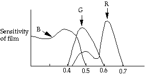
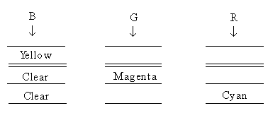
Figure 3.7 shows the structure of the three emulsion layers for a color negative film. Figure 3.8 shows the spectral sensitivities of each emulsion layer of the film. It can be seen from Figure 3.8 that green and red emulsion layers are also sensitive to blue. Therefore, film producers add a yellow filter to stop the blue lights from reaching the green and red emulsion layers (Figure 3.7).
Figure 3.7. Layers in a stadard colour film

Figure 3.8. The approximate spectral sensitivities of the three layers.
The development procedure for the colour negative film is shown in Figure 3.9.
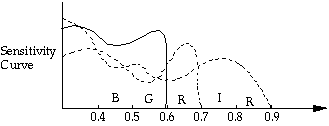
The sensitivity curve of a colour infrared film is shown in Figure 3.10. Figure 3.11 shows the structure of this type of film.
As the light of three primary colors pass through the film

After film development
Yellow
Magenta
Cyan
Print with white light
RGB
RGB
RGB
Y M C
RG through
RB through
GB through
Y Y M M C C The results are:
B G R Figure 3.9. The development procedure of a colour film

Figure 3.10. The sensitivity curves of a colour infrared film
Film
Dye
NIR + B (Cyan dye forming layer)
G + B (Yellow dye forming layer)
R + B (Magenta dye forming layer)
Figure 3.11. Three layers of a colour-infrared film
The CIR film development process is as the following:
Photography
B G R IR
| Clear | C | ||
| Clear | Y | ||
| Clear | M |
Use of white light to pass through the developed film
BGR BGR BGR BGR
| Clear | C | ||
| Clear | Y | ||
| Clear | M |
Colour photographic paper exposure
| Y | Y | Y | |
| M | M | M | |
| C | C | C |
Final result
| Black | B | G | R |
Figure 3.12. The procedures used to develop a colour film.